Home \ Articles \ RAID 101

RAID 101

ZAR has been discontinued
After about twenty years, I felt ZAR can no longer be updated to match the modern requirements, and I decided to retire it.

ZAR is replaced by Klennet Recovery, my new general-purpose DIY data recovery software.

If you are looking specifically for recovery of image files (like JPEG, CR2, and NEF), take a look at Klennet Carver, a separate video and photo recovery software.
General notions
RAID is short for "Redundant Array of  Inexpensive (or Independent) Disks", originally opposed to "Single Large Expensive Disk" (SLED). In RAID, data is distributed between several physical disks (called "Member Disks") to provide additional reliability and/or speed increase. There are several "RAID levels" different in data placement algorithms (see below). The array of disks is presented to the operating system as a single large disk so that operations with RAID array do not differ from the operations on the regular device with respect to the file storage (and filesystem drivers in general).

RAID is implemented either by the driver (this is called "software RAID") or by the special hardware controller ("hardware RAID"). Both Microsoft Windows (except Windows 9x) and most flavors of Unix/Linux provide their software RAID implementations.

RAID does not provide perfect reliability
RAID, no matter how redundant, does not substitute proper and regular backups.

Consider the following points:

  • Multiple drive failures do happen, especially if caused by the single source (for example a power supply unit goes bad and spews 220 volt AC current over the 5V DC power bus - this will take out all the drives powered by that PSU).
  • The entire array may be lost due to the controller failure.
  • Virus can take out data on the array. The array will be still functional with respect to its hardware, but the data will be of no use.
  • Fire or natural disaster (like flood) can take out the whole array.
  • Operator error can cause damage to data or RAID misconfiguration.
JBOD (Just a Bunch Of Disks), also called "Span"/"Spanned Volume"
This is not a RAID in the strict sense, because JBOD does not provide any redundancy. If any of the drives in the JBOD-type array fails, the whole array fails and all data on it is lost. Typical usage of JBOD layout is just to create a disk of larger capacity by merging two or more smaller disks. This is only practical if the disks have different capacity. For the disks of equal capacity, RAID 0 is better because it provides the same capacity increase, the same non-redundant layout with no disk space overhead and features faster read/write speed in typical applications. JBOD can provide speed increase if two operations are requested simultaneously on data blocks that are stored on different drives, but this is relatively rare situation (let's say for example that read of blocks D1, D2, D3 and D11, D12 is requested simultaneously; in such a case two requests can be performed in parallel, increasing overall I/O speed).

Minimum of two disks is required for a hardware JBOD. Minimum of one disk is required for a software JBOD (Windows "Spanned volume", which allows volume to occupy nonadjacent regions of the same physical disk). There is no disk space overhead. The following exception may or may not apply in your case: hardware RAID controller may support a single-disk JBOD configuration - this is just a trick to allow a single drive to be attached to the controller, without actually RAIDing anything. The same applies to RAID0 consisting of 1 member disk.

JBOD (Spanned volume) layout

RAID 0, also called "Stripe Set"
This one again is a "non-redundant" RAID. RAID0 fails if any member disk of the array fails. Major benefit of RAID 0 is that it provides N times I/O throughput increase for N-disk configuration. The read/write requests are scattered evenly across member disks, so they can be executed in parallel. For example, if write of data blocks D1 through D6 is requested odd blocks (D1, D3, D5) should be written to Disk 1 and even blocks (D2, D4, D6) should be written to Disk 2, which doubles the overall operation speed.

Minimum of two disks is required for a RAID 0 setup. There is no disk space overhead associated with RAID 0 volume. The following exception may or may not apply in your case: hardware RAID controller may support a single-disk RAID0 configuration - this is just a trick to allow a single drive to be attached to the controller, without actually RAIDing anything. The same applies to JBOD consisting of 1 member disk.

RAID0 (Stripe set) layout

From the recovery point of view, RAID0 requires all the disks present since there is no redundancy. More information about how to recover RAID 0 configuration you can find on the RAID0 recovery page.

RAID 1, also called "Mirror"
In a mirrored volume, two exact copies of data are written to two member disks. Thus, a "shadow" disk is an exact copy of its "primary" disk. This layout can tolerate loss of any single disk (read requests will be satisfied from the functional disk). A mirrored volume features twice the read speed of a single disk: when requested to read data blocks 1 through 6, the mirror routes odd blocks (D1, D3, D5) to be read from Disk 1 and even blocks (D2, D4, D6) from Disk 2 so that each disk does half of the job. Write speed is not improved because all copies of a mirror need updating.

It is possible to have more than two disks in the mirrored set (e.g. three-disk configuration - "primary" with two "shadows"), but such a setup is extremely rare due to the high disk space overhead (200% overhead in three-disk configuration).

Exactly two disks are required for a RAID 1 volume. RAID 1 layout imposes 100% storage space overhead.

RAID 1 (Mirror) layout

RAID 5, also called "Stripe Set with parity"
RAID 5 utilizes a parity function to provide redundancy and data reconstruction. Typically, an "exclusive OR" ("XOR") binary function is used to compute parity for a given "row" of the array. Anyway, the parity is computed as a function of several data blocks P=P(D1, D2, ... DN-1) for N disk layout. In case of a single drive failure, the inverse function is used to compute data from the remaining data blocks and parity block.

Let's say for example that the Disk 3 fails in configuration illustrated below.

  • Data blocks D1 and D2 will be read directly from their corresponding disks (which are operational).
  • Parity block P1,2 is really not needed (does not contain user data) so it will be just discarded.
  • Data block D3 will be read from its corresponding disk (Disk 2).
  • Data block D4, which is missing because its drive is offline will be reconstructed using D3 and P3,4 like this: D4=Pinverse(D3,P3,4).

During normal operation, read speed gain is (N-1) times, because requests will be evenly routed to N-1 disks (parity read is not needed during normal operations). Write procedure is more complicated, and actually imposes some speed penalty. Let's say we need to write block D1. We also need to update its corresponding parity block P1,2. There are two ways to accomplish this:

  1. Read D2; compute P1,2=P(D1,D2); write D1 and P1,2;
  2. Read D1;old and P1,2;old; compute P1,2 from these data; write D1 and P1,2.

Both of these ways require at least one read operation as the overhead. This read operation can not be parallelized in any way with its corresponding write operation, so write speed should decrease (by the factor of two, assuming equal read and write speed). Most current implementations mitigate this effect by maintaining the entire "row" (D1, D2 and D3) in the cache.

Minimum of three disks is required to implement RAID5. Storage space overhead equals the capacity of a single member disk and does not depend on the number of disks.
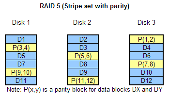
RAID 5 (Stripe set with parity) layout

Unlike a RAID0, RAID5 can be recovered with one disk missing; please refer to the RAID5 recovery page for more details.

RAID 0+1, also called "Mirrored Stripe Set"
This layout combines speed efficiency of the RAID 0 (stripe set) with a fault tolerance of RAID 1 (mirror). Its only drawback is the 100% disk space overhead.

For N-disk configuration (with two stripe sets with N/2 disks each)

  • N times faster reads, compared to a single member disk (request to read blocks D1 through D4 will be routed in such a way that each member disk reads one block).
  • N/2 times faster writes, compared to a single member disk (write request to blocks D1 through D4 will be routed so that Disks 1 and 3 write blocks D1 and D3 and Disks 2 and 4 write blocks D2 and D4, thus doubling a write speed in 4-disk setup).

The RAID 0+1 array can tolerate a loss of any single disk. Additionally, it can handle half of the dual failures in the four-disk configuration (e.g. if disks 1 and 2 fail in configuration illustrated below, the array will still be online albeit degraded to a stripe set).

Minimum of four disks is required for a RAID 0+1 volume, with a 100% storage space overhead.

RAID 0+1 (Mirrored stripe set) layout

Other (exotic) RAID layouts

Quite a number of other (exotic) types of RAID exist, but they are rarely used and detailed discussion of those is outside the scope of this article.

  • RAID 3 and RAID 4 are similar to RAID 5 but use dedicated disk to store parity information. This disk becomes a bottleneck during write.

  • RAID 6 is similar to RAID 5 but uses two different parity functions to maintain redundancy. RAID6 can tolerate a dual failure (simultaneous loss of two drives). RAID6 is useful in high-capacity systems when the rebuild of a RAID5 volume would take a long time and there is a significant probability that another drive will fail before the rebuild is done, thus causing a loss of the array.

Hot sparing and/or mirror reliability issues
Some fault-tolerant implementations allow the additional drive to be designated as a "hot spare". Once the drive in the array fails, the "hot spare" drive is used to rebuild the array and restore the redundancy as soon as possible, allowing to defer the maintenance action (failed drive replacement) e.g. till working hours. There is a quirk involved. The controller must implement some periodical checks of the "hot spare" drive. If the bad sector develops on the "hot spare" and goes unnoticed, the spare drive will be essentially useless when one of the member disks fails. Should the "hot spare" drive fail completely it will be noticed once the controller discovers it is unable to interrogate the device. Bad sectors cannot be detected this way and will sit there unnoticed until it is too late.

The same consideration applies to RAID 1 (mirror) setup. The controller should interleave the requests so that both drives get their share of reads. This way, if a bad sector develops on one of the drives, it will be soon discovered (this is sometimes called "active/active" fault-tolerant implementation). If the "active/standby" scheme is implemented, reading a primary drive and falling back to the shadow drive only when primary one goes bad, it is possible that shadow will develop unnoticed bad sectors and once the primary drive fails, the backup would be already damaged.

Estimating RAID capacity, access speed and fault tolerance

RAID planning can be done by hand using the table provided below. We've also created the online RAID estimator tool which will do the job provided just the array layout and member disk sizes.

RAID type (level) reference table

RAID Type

Number of disks required

Fault-tolerance

Speed increase with N disks in the array*

Disk space overhead**

JBOD (Span)

2+

None

Uncertain (heavily depends on the volume layout). No significant increase in typical applications.

None

RAID 0 (Stripe)

2+

None

N times increase on both reads and writes

None

RAID 1 (Mirror)

Exactly 2

Single disk failure

Double speed on reads;
No gain on writes

100%

RAID 5 (Stripe with parity)

3+

Single disk failure (this will cause read speed to degrade)

(N-1) times increase on reads;
up to 2x loss of speed on writes

A capacity equivalent to that of one member disk is used to hold checksums

RAID 0+1 (Mirrored stripe set)

4+

Single disk failure; half of dual disk failures, depending on the location/assignment of failed drives.

N times increase on reads;
N/2 times increase on writes

100%

*Note: speed increase is a very rough estimate based on the assumption that disk traffic consists mostly of linear (sequential) reads of large data chunks. This estimation also assumes controller is capable of overlapped operations and there are no problems with bus throughput (since several RAIDed high-performance drives can easily saturate the bus like PCI).

**Note: disk space overhead calculation is based on the assumption that all member disks are of equal capacity. If the disks are not equal in size, the smallest disk will be used as a "column" size.

Copyright © 2001 - 2024 Alexey V. Gubin.